|
I have been playing with micro:bit and various shields/hats to have easy access to the pins for robotics purposes. Most recently I worked with bit:booster from electrify (video links at bottom). It costs $35. It has a nice form factor, being just a little bit larger than the micro:bit. They made the pins on the sides large enough to fit Lego pieces. 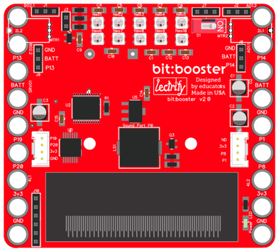 They have some good features. The battery pack (3 AA) is mounted on the back to supply 4.5 volts for motors, servos, neopixels and sensors. They use voltage regulation to send only 3V to the micro:bit. There is an on/off switch. They have 2 sets of pins designated for servo’s and 2 other sets for motors. They also have 10 neopixels on the board and pins to hook up a neopixel strip. They have 2 grove ports to attach some sensors. They also have pin outs for “extra” pins (more later). Finally, there is a piezo buzzer for some sound from the micro:bit. lectrify has created great starter cards showing you how to hook things up and how to start the code. 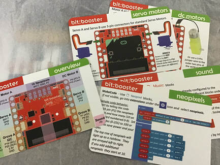 About those extra pins. I want to use them for external switches/buttons, besides the A & B buttons on the micro:bit. After a bit of research I found out that they are part of the LED matrix on the micro:bit and if you want to use them otherwise, you have to disable them. This is easily done with one block of code under the “Led” set in makecode , "led enable false". There is a video in my playlist how to use them for a switch.  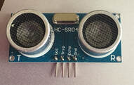 I also wanted to play with some more sensors, so I started with the HCSR04 ultra sonic distance sensor. This was a pain at first. I tried using the grove ports, then the “extra pins” to no avail. Did a bunch of research and found out that it needs almost 5V to work (grove and “extra” only put out 3V). I verified this using a 5V grove port on another shield. I thought I should be able to use the “BATT” near other pins like the neopixels as it should be 4.5V, but I must have been doing something wrong. After contacting Diego at lectrify he mentioned that I should be able to do that and mentioned the servo ports. So I tried that the next day, using BATT, GND and P13 from one port and P14 from the other port. Success!!! (yes there is a video or two).
There are two extensions that I added to the blocks for this. One was “Sonar” and the other was “Makerbit”. Sonar only has one block, it is to designate the signal pin, the echo pin, and units of measure. The Makerbit has a block under Ultrasonic , “connect ultrasonic….”. It seemed like it should be helpful to initialize the setup. I will have to check if it is necessary to have both. Coding was frustrating at first (nothing to do with the bit:booster). I was trying to get some if’s to trigger neopixels based on distances and that was not happening. So I went basic and had the micro:bit LED matrix just show the number the sensor was getting. After I knew that was working I added an if and it worked. That is the logical thinking part of programming, how to make happen what you want to happen. I don’t know what else to add to the bit:booster right now. Maybe try to add another speaker output. But I don’t think that is possible because micro:bit defaults sound to P0 and there is no access to that. Maybe a 2 line LCD screen, or an actual micro switch (which i don't have yet), or a potentiometer (dial). I like the bit:booster. It is easy to work with. I think they need a few more cards (distance sensor, how to use extra pins, what about the pins they don’t mention, one or two other sensors. Remember, for all physical computing you need jumper cables, all three types (M-M, M-F, F-F) and alligator clips. Here is a link to my video playlist exploring the bit:booster : https://www.youtube.com/watch?v=X9LwKxbajaU&list=PLo6W7Aw8EPRC7P7cIaMFe9sIkBqdXD6BM
0 Comments
Your comment will be posted after it is approved.
Leave a Reply. |
Archives
December 2022
Categories |
 RSS Feed