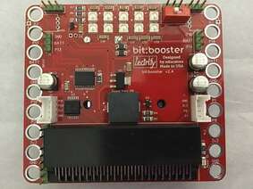
bit:booster
The bit:booster by lectrify is a $35 general breakout board (hat/shield) for the micro:bit. I call it general because it gives you access to most of the pins for a variety of purposes. They have nice documentation with some good starter cards on how to connect 4 devices (servo motors, motors, neopixels, sound) and start coding them. I think they could use a couple of more cards for some basic devices most people will use. In particular I would like cards for ultrasonic distance sensor, 16x2 LCD screen, external switch, potentiometer.
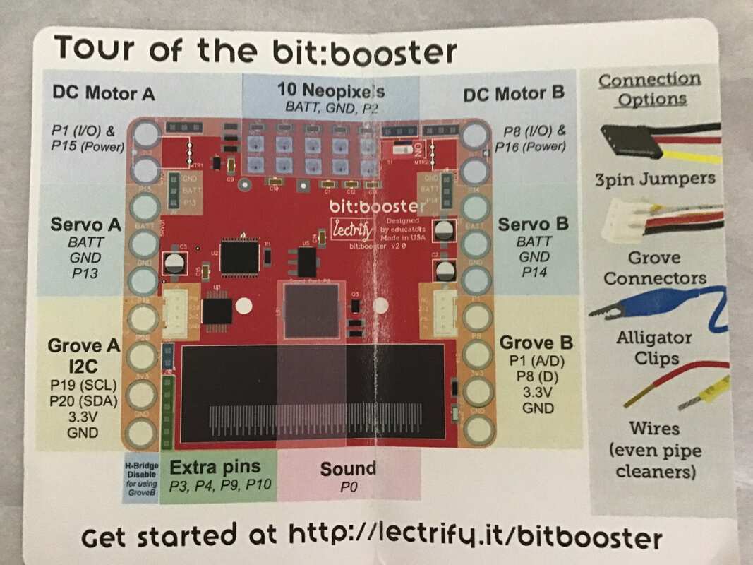
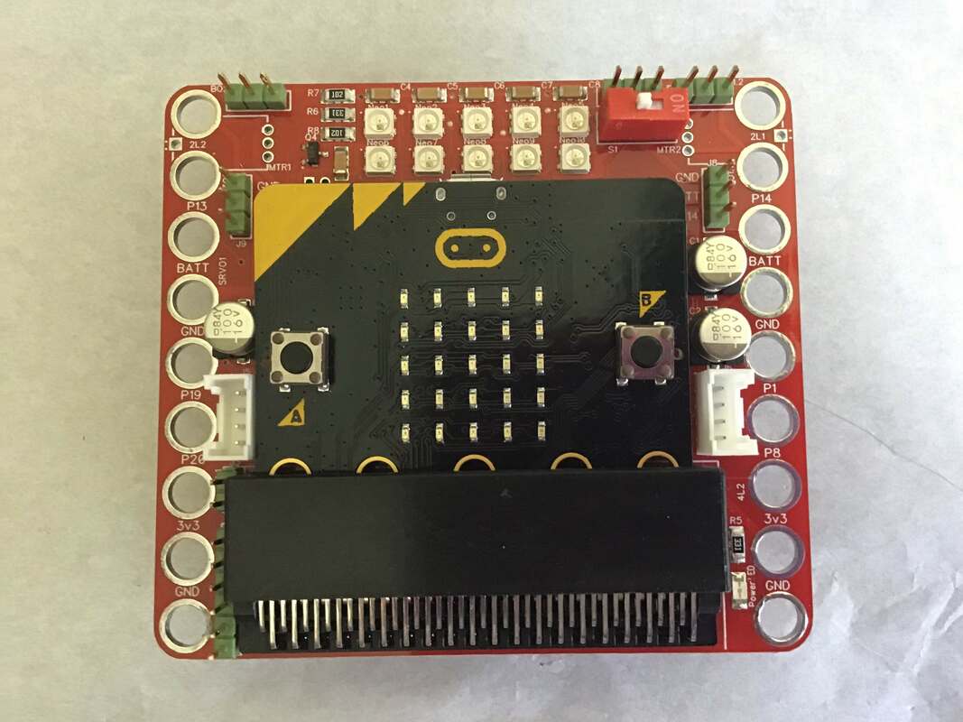
Let us start at the top middle with those 10 neopixels. It is nice to have some lights on a board. They are connected to pin 2. To their right is green block of 3 pins (P2, BATT, GND) where you can attach a neopixel strip. Just remember that there are already 10 neopixels hardwired and addressed as neopixel 0-9, so a strip would start at neopixel 10 (remember things start with an address of 0). Below that is a very important on/off switch. The top left & top right corner triple green blocks are where you plug in motor A & B (pin 1 & 15, pin 8 & 16). Notice there are three pins to plug in to, but you only need two for a motor...use the 1st and 3rd pin.
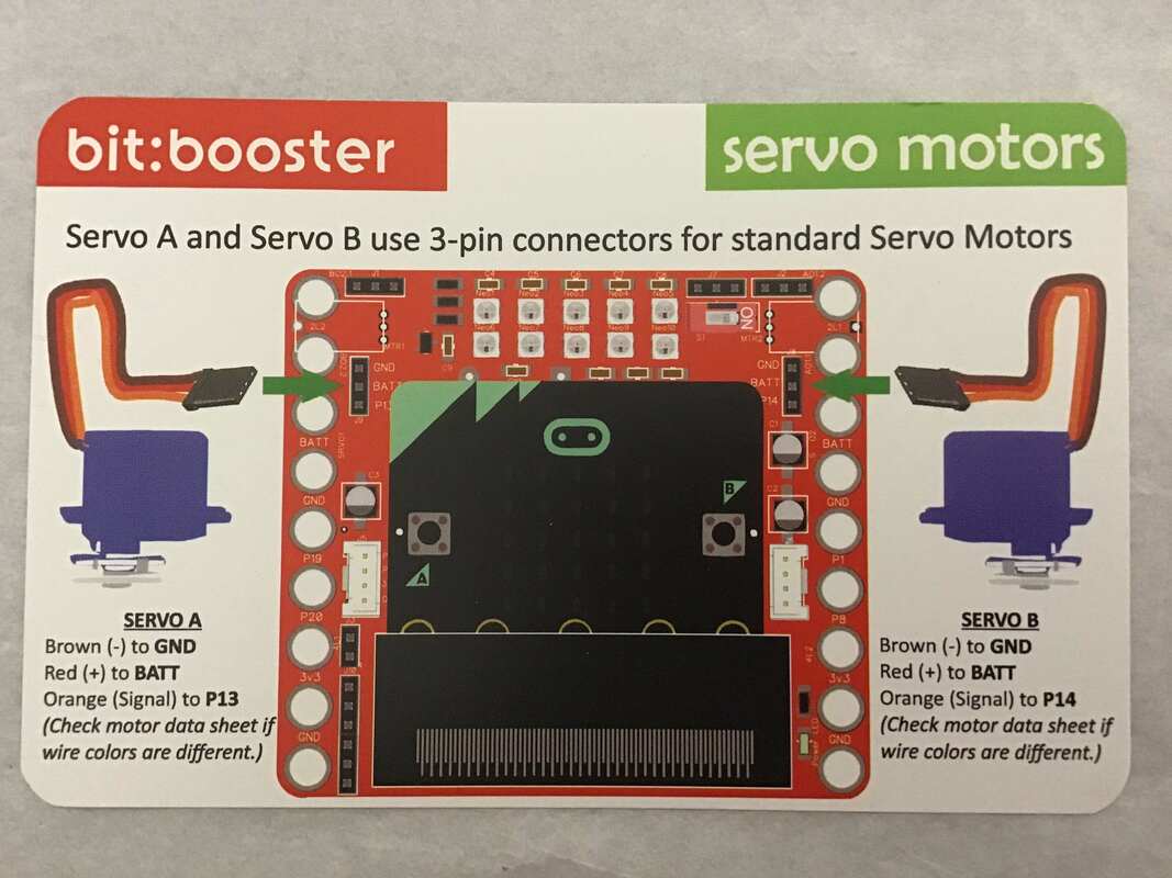
There are two other triple green blocks near the top, one on the right and one on the left. Those are for servos and they use pin 13 & 14. There are two white blocks, one on each side. These are grove connectors for easier connection to some devices that use 4 pins. The one on the left is for I2C devices and uses pins 19 & 20. The one on the right uses pins 1 & 8. These only supply 3V, so not all devices will work (an LCD needs 5v)
Finally, the big square black box in the "middle" of the board is a piezo speaker. The micro:bit uses only pin 0 for sound. I wish they gave us a way to access pin 0 for our own speaker.
It is probably handy to have the overview diagram side by side with the board. Though just because it says to plug servo in to P13 does not mean you can only plug a servo in there. You can plug any device that needs BATT , GND and a digital pin.


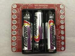
They have a 3 AA battery pack on the back of the device. Because of the form factor of the board (just bigger than the micro:bit) I don't think they could have gone with 4 AA's. In some ways I would like more than 4.5 V to better run some things, for example a 16x2 LCD. But I do like NOT having to hunt for a battery pack. The big rings on the sides are actually pins that you can connect to, but they are the same pin numbers as used in the connectors. Also the rings are the size of a Lego stud.
You might be keeping track and noticing that green block to the left of the micro:bit block.
We have not used all 25 pins that are on the micro:bit. They are trying to avoid any conflicts with the A & B button (pin 5, pin 11) as well as the 5x5 LED array (pin 3,4,6,7,9,10).
Now if you need more pins, you can use that green block , labeled "extra pins", for pins 3,4,9,10.
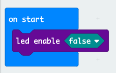
But you will have to "disable" the 5x5 LED array with a simple line/block of code "Led enable false"
You will want to buy jumper wires. You might as well get the triple pack (F-F, M-M, F-M). Pay attention to the length as you buy these (10 cm is roughly across your palm). You will probably also want grove connectors and alligator clips wouldn't hurt, even alligator to F wires.
You might be keeping track and noticing that green block to the left of the micro:bit block.
We have not used all 25 pins that are on the micro:bit. They are trying to avoid any conflicts with the A & B button (pin 5, pin 11) as well as the 5x5 LED array (pin 3,4,6,7,9,10).
Now if you need more pins, you can use that green block , labeled "extra pins", for pins 3,4,9,10.
But you will have to "disable" the 5x5 LED array with a simple line/block of code "Led enable false"
You will want to buy jumper wires. You might as well get the triple pack (F-F, M-M, F-M). Pay attention to the length as you buy these (10 cm is roughly across your palm). You will probably also want grove connectors and alligator clips wouldn't hurt, even alligator to F wires.
|
|
<<<<<< An introductory video to the bit:booster.
Here is a link to the playlist of several videos using hte bit:booster. https://www.youtube.com/watch?v=X9LwKxbajaU&index=2&list=PLo6W7Aw8EPRC7P7cIaMFe9sIkBqdXD6BM&t=0s www.youtube.com/watch?v=X9LwKxbajaU&index=2&list=PLo6W7Aw8EPRC7P7cIaMFe9sIkBqdXD6BM&t=0s. |