|
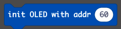
More playing around with the #microbit & #makecode. I started looking into using a 0.96" OLED screen for output from a micro:bit (and a 4x4 matrix membrane keypad for inputs)...so here are some beginning thoughts about the OLED... 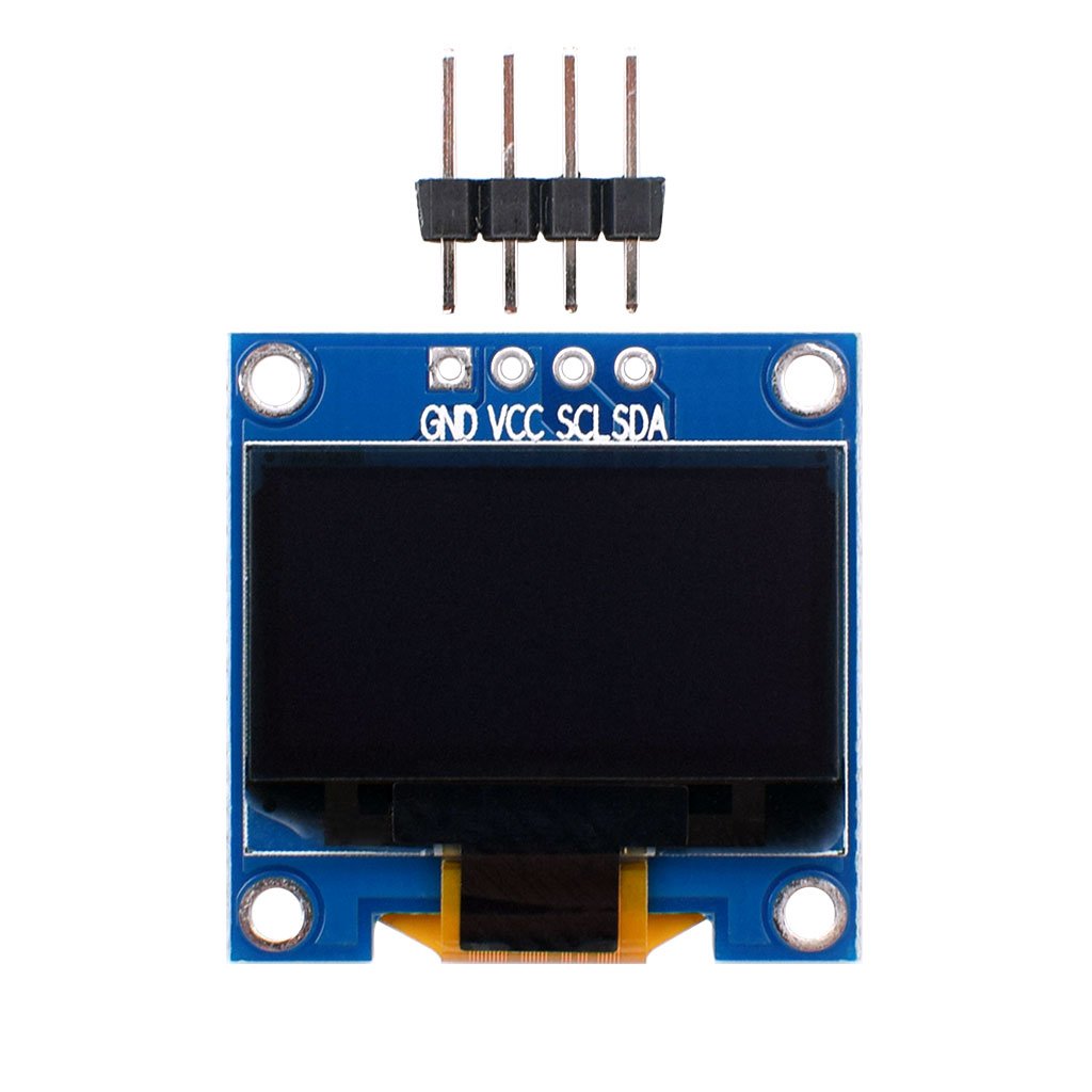  OLED stands for organic light-emitting diode (OLED or organic LED), sometimes known as organic electroluminescent (organic EL) diode. Most often I see two size/resolutions , 128x64 and 128x32 pixels. I have played with the 128x64. The text can be white, blue, yellow, or some combo of those and they cost from $4-7 based on how many you buy on Amazon. I prefer to buy ones with the headers already attached (I don't want to solder). You need an expansion board for the micro:bit because you need access to pins 19 & 20 There are many available, ranging from $7 to $50. They all have different features, as well as different power inputs jacks (jst, micro USB, barrel). Some have pins/sockets to connect to the pins, some have grove connectors... so you will also need the correct wires. 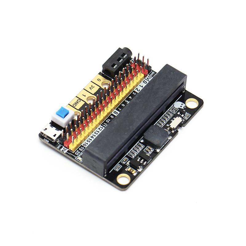  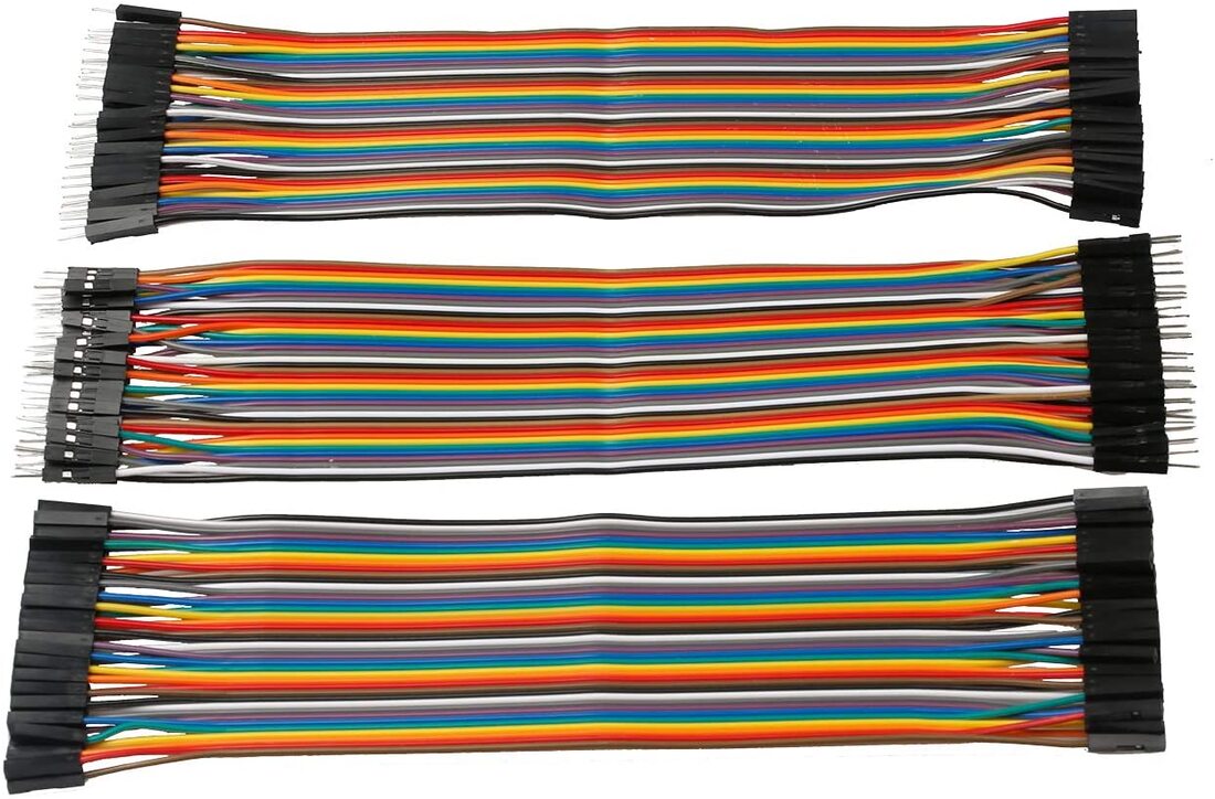 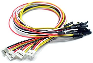 Connections... be careful. Always plug GND in first and remove it last (a best practice). Pin 19 is the SCL (serial clock) connection and Pin 20 is the SDA (serial data) connection. The Grove I2C connector (white plugs & cables) has a standard layout. Pin 1 is the SCL signal (serial clock) and Pin 2 is the SDA signal (serial data). Power is Pin 3 and Ground is Pin 4 (usually in the order white, yellow, red, black) Some devices don't adhere to this order. That is why it is good to have a grove-header pin converter cord vs a grove-grove cord Look at the OLED... it goes SDA, SCL, PWR, GND. You need to import the blocks for this device from an extension in makecode { https://makecode.microbit.org/ } Start a "New project” Use either the gear in top right or “Advanced” to get to “Extensions Search for “oled” The second one has more options  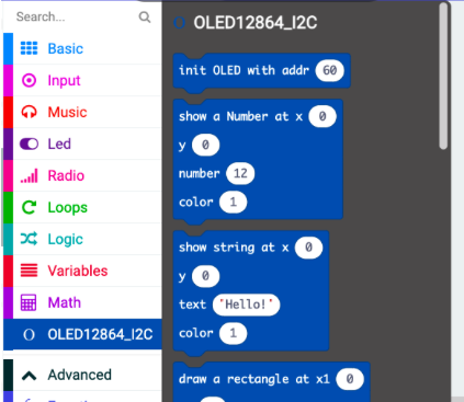 There are some nuances you have to understand for things to show up correctly. The origin (0,0) is at the top left 128x64 pixels means x pixels numbered from 0-127 and y pixels numbered 0-63 So pixel (0,0) is in top left corner ; pixel (127,63) is in bottom right corner. There are 8 lines of text possible with 24 characters each (text, numbers) BUT... There is a "zoom" feature, and 128x64 is when "zoom=false". Because those 8 lines of text are tiny, they added a "zoom = true" block to double the size of text. When "zoom=true" there are 4 lines of 12 characters. That also means x goes from 0-63 and y from 0-31.
Now it is just a matter of what you want to display... Built in sensor data like temperature, light level, accelerometer, sound? Values for variables? (almost forgot-they have an option for "color" -- the options are 0 or 1. see which you prefer) You can make a line graph by plotting pixels. Basically, you will light up pixels at (x, value) and just iterate the x from 0-127 (or 0-63) Two things to think about/do 1) since the origin is top left, i feel it is easier to turn the OLED upside down and iterate x from 127-0 (go by -1)(or 63-0) 2) You need to map your sensor values to the screen size (63 or 31 depending on zoom) You need to know what values your sensor can detect (0-255? 0-1023? 0-10?) There is a block for that...but you also want to round the values (get integer values) 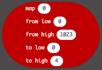  Here is an example : 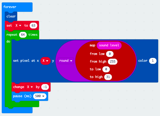 I will make some videos soon...
0 Comments
Your comment will be posted after it is approved.
Leave a Reply. |
Archives
December 2022
Categories |

 RSS Feed